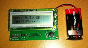
Transistortester
Ein unentbehrliches Hilfsmittel in der Bastelecke ist ein universelles Testgerät für
- Transistoren
- FETs, Thyristoren, Triacs, ..
- Dioden, Z-Dioden, …
- Widerstände
- Kondensatoren incl. ESR-Messung
- Spulen
Die bestückte Platine ist für 10..20 Euro bei Ebay erhältlich (Booster edition, Transistor-L/C ESR Tester oder auch Transistor Tester Capacitor ESR Inductance Resistor Meter NPN PNP Mosfet).
Die eigentliche Entwicklungsarbeit stammt von Karl-Heinz Kübbeler, http://www.mikrocontroller.net/articles/AVR_Transistortester. Über diesen Link ist auch ein ausführliches 80seitiges (deutsches) Handbuch und die aktuelle Firmware zu beziehen.
In einem Forum habe ich eine Analyse der China-Version im Vergleich zum Original gefunden. Es gibt hierin ein paar Hinweise, wie man das Gerät verbessern kann. Im Handbuch Version 1.06 (und neuer) wurde ein Unterkapitel China Clone im Hardware-Kapitel ergänzt.
------------------------------------------------------------------------------
http://www.diyaudio.com/forums/equipment-tools/224329-another-ebay-gadget-2.html
------------------------------------------------------------------------------

 23rd December 2012, 07:07 AM    #17
 kubi48
diyAudio Member


Join Date: Dec 2012  Results of analysing the china version

--------------------------------------------------------------------------------

I had got one of the first series. The board is called "Booster edition Ver 2.1
2012/11/06", Transistor-L/C ESR Tester. The board with the LCD display was
delivered without any documentation!
The label of the ATmega is not readable. But I had added the 10 pin ISP
connector to the board. I had added a additional GND connection to pin 10 of the
ISP connector too. So I could check, that there is a ATmega168 or ATmega168A
installed on my board. I am not sure if the installed 8 MHz crystal has been
used by setting the right fuses of the ATmega. The original software was my
version 1.02k . I have flashed my version 1.04k and set the fuses to crystal
operation. On my board a 2.5V zener diode was connected to pin PC4 of the
ATmega. I had measured a voltage of only 2.2V. I have replaced this zener diode
by a LT1004 precision voltage reference (2.5V) as originally designed. Next I
have done a self test by connecting all three pins together. Integrated with the
self test is a automatic calibration. You need a external capacitor with a
capacity of 100nF - 20uF connected to pin 1 and pin 3 to finish the calibration.
At test step 4 you must disconnect the pins.
The capacitor must be connected with the display message
"1-||-3 >100nF" in row one.
After all this work I have noticed, that a direct connection of two pins
together results to a resistor message with a result of 0.3 Ohm. I have checked
with my LCR meter, that one signal path from test pin to the pin of the SMD
ATmega has a resistance of 0.15 Ohm. This resistance is much more than the one
of all prototype boards and is not compensated by the software.
This will be the reason of the different ESR measurement results of this board
version. I don't know, if some of the bugs are eliminated with the newer Chinese
board version.

Best regards,
Karl-Heinz

------------------------------------------------------------------------------

3rd December 2012, 07:22 PM    #6
 kubi48
diyAudio Member


Join Date: Dec 2012 I would like to tell you, that the china transistor tester
with ESR and inductance measurement is copied from the german internet side AVR
Transistortester - Mikrocontroller.net . At the end of this side you find a
download area for software and PDF documentation. The project has been started
by Markus F. and I had added some new features. It is free software, anyone can
use it.
You will find in the documentation (also in english language) information about
measurement principle and results. I hope, that my english was good enough to
explain all.
Regards
Karl-Heinz Kübbeler
Sinzig, Germany
